Vibration motor analog sensor(kind of)

I had a difficult time with this. I believe my problem was somewhere in the Arduino code but I couldn’t determine where in time. Essentially, the analog sensor functioned inversely, so the super tiny vibration motor I used for output would run when the analog sensor was not touching the copper tape, and turn off once touching the copper tape.

IMG_1553

Overall setup ^

IMG_1551

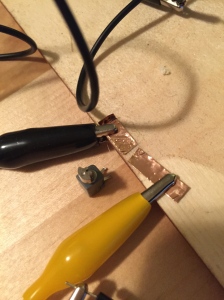
(Vibration motor had very tiny prongs, which I would touch to the two separate pieces of copper tape that had the clamps. Yellow = digital pin 11, Black = GND)

IMG_1549

(Vibration motor off ^)

IMG_1550

(Vibration motor on^)

Here is my Arduino Code

Brooks D’Antonio Potentiometer Button

For this project creating a Arduino analog switch I decided to use scrap parts from work. I went with a BNC connector and a coin battery holder as the button to power an LED light. Utilizing the Lillypad Arduino and alligator clips in theory thus would turn on the light with the simple touch of the button.

Below is a rough sketch of the circuity diagram.

Diagram / Example:

IMG_7127 IMG_7131

Code:

int analogPin = A0;
int Value = 0;
int ledPin = 9;

void setup() {
pinMode(analogPin, INPUT);
pinMode(ledPin, OUTPUT);
Serial.begin(9600);
}

void loop() {
Value = analogRead(analogPin);
int motorValue = map(Value, 700, 1023, 0, 255);
analogWrite(ledPin, motorValue);
Serial.println(Value);
delay(1000);
}

Analog sensor

I created a set of three buttons that control volume. My original idea was to have them play different tones so you could play Mary Had a Little Lamb with the sensor, but I have only partially figured out how to program notes.

2015-02-03 20.52.21

Arduino bend sensor

I used aligator clips and conductive wool for resistors and conductive fabric/thread for the bend sensor. Took awhile to wire everything together but i eventually figured it out. The piezo sound didn’t change in the way i thought it would but it did change when i used the sensor. i finished everything on before midnight but the video uploading took a long time due to slow internet.

Code:

Capture

Sliding Potentiometer – Alex Marquez

For my analog sensor, I created a sliding potentiometer that sits on top of a box which holds a buzzer. The buzzer is the main output but I also wanted to add a visual output just to see whats going on, so i’ve attached an LED to the same pin. The sensor is made up of conductive yarn thats hooked up to the 5V and GND, and conductive fabric thats hooked up to A0.

Here is the code used for this assignment.

And here is the video demo.

SoftPotentiometer_bb

Proximity Sensor – Alex Stabinski

For this project i originally wanted sort of a circular track where you had 2 cars that would be able to move around and as one got closer music would get louder as the two cars got closer together.

I had problems with both the sensing and sound as I found out i needed an Ardunio extension that allows you to insert an SD card and play files from it through a speaker.

So what i ended up doing was simply focusing on having 2 different points that you place upon a circuit that would be able to light an LED when they get near each other.

the “track” ended up connecting only to ground, while one point would hold the voltage. That way the position is relative to the points ( in this example the cars) rather then the track. The sensor is then attached to the other car to measure if its close to the beginning of the circuit ( the other car) and the other end of the circuit.

It still had some current problems, but it eventually worked as intended for a short while….

Video – http://youtu.be/HD09MbSTdpc

Code –

20150203_132629

Analog Sensing (Buzzing Box)

For this assignment I wanted to use a different Arduino and materials than what I’ve used in the past two assignments. I decided mainly upon a Lilypad and conductive thread.

If you watch the video below, I’ve got a piezo that only buzzes when the top of the box is completely put onto the bottom of the box to let you know the top is fully on. I was able to make a potentiometer and measure how far down the box is and made it so that when the top of the box is measured at the bottom position, the piezo will buzz. Anything else than that bottom position, the piezo will remain silent and the serial monitor will be just tracking the measurements instead.

Since we haven’t messed with piezo’s before this was a big feat for me to make it at least work in some way with analog sensing. So even though there isn’t a variable as far as pitch or loudness of the buzzing, I intend to learn how to do that with a piezo as the course continues.

Here is the code I used for this assignment.

– Jordan Sussman

Gabe’s Painted Potentiometer

20150203_115622 potentiometer

Once again substituting traditional materials with less obvious objects, I explored creating a painted potentiometer with a strip of conductive silver paint and a piezo functioning as the output mechanism. Attached to either end of the paint strip were paperclips clamped with alligator clips (this connection proved too direct overheating multiple elements, so needing more resistance I used conductive yarn as a medium between the paper clip and the alligator clip). Acting as the sensing mechanism was a paperclip tied to conductive yarn leading back to Analog pin 0, so when sliding the sensing paperclip along the strip of paint the current was higher towards the 5volt end and lower the closer to ground. Sliding the A0 paperclip back and forth along the painted strip effected the intensity of the piezo’s physical and sonic vibration, picking up frequency as the clip neared the 5volt source and losing frequency the closer to ground the paperclip was.